
A pool does not work because of the pump — it works because of the circuit. The pump is just one link in a path that starts at the skimmer and the main drain and ends at the jets, and the weakest point of that path determines the result. This is why an undersized suction line cannot be “out-pumped” with a stronger motor, and why the water around the steps stays cloudy even with perfect chemistry. This article explains what flow velocities the pipework should stay within, when 50 mm sizing is enough and when 63 mm is necessary, why every elbow costs performance, and how to place the jets so that no dead zones form in the pool.
What is a pool hydraulic circuit?
The recirculation circuit is a closed loop that the water passes through several times a day. It has a fixed order and every element in it has its place:
- Suction — the skimmer (draw-off from the surface) and the main drain (draw-off from the floor), usually at a ratio of roughly 50 : 50 in a private pool.
- Pre-filter and pump — the only source of energy in the circuit.
- Filtration — a sand or cartridge filter, usually via a multiport valve.
- Heating — a heat pump or heat exchanger, always downstream of the filter.
- Disinfection — a dosing unit, salt chlorinator, UV or ozone, as a rule the last element before the return to the pool.
- Discharge — the return pipework and the recirculation jets.
The crucial point is that the water must return to the pool in such a way that it pushes the untreated water towards the suction. Otherwise you keep filtering the same part of the volume and the rest stands still. That is hydraulics: not how much water the pump moves, but from where to where it moves it.
Flow velocity: the number that decides everything else
Pipe diameter is not derived from the connection threads of the pump or the filter — those have nothing to do with the design. It is derived from the required flow rate and the maximum permissible flow velocity. According to the technical guidance of Astral Pool CZ (Calculation of the basic technological equipment of a pool), the flow velocity in the suction pipework must not exceed 1.2 m/s, and in the return (discharge) pipework it ranges from 1.8 to 2.0 m/s. Foreign regulations are more lenient — the American International Swimming Pool and Spa Code sets a limit of 1.8 m/s on the suction side and 2.4 m/s on the discharge side for public pools. A safe design stays at the lower end; the difference between 1.2 and 1.8 m/s on the suction side is typically the difference of one pipe size and a few tens of euros’ worth of material.
Why is a lower velocity used on the suction side than on the discharge side?
Upstream of the pump there is negative pressure in the pipework. The faster the water flows there and the greater the resistances, the further the pressure drops — and once it falls below the saturated vapour pressure, the water in the suction line starts to evaporate into microscopic bubbles. These then implode in the impeller. This is called cavitation and it shows up exactly as described in forum discussions: the pump sounds as if it were pumping gravel, it vibrates, air is visible in the pre-filter and the flow fluctuates. In the long run this destroys both the impeller and the shaft seal.
Downstream of the pump there is positive pressure, so cavitation is not a risk there — which is why the velocity can be higher. Even here, though, exceeding the limit has a price: noise and vibration, pressure surges when valves are closed (which mainly damage the filter) and steeply rising losses. Pipe resistance grows roughly with the square of the velocity — twice the velocity means approximately four times the loss.
50 or 63 mm? Which size when
The following table shows how many m³/h a given size of PVC-U pipework (PN10 series) can realistically carry at the recommended velocities. The values are calculated from the internal diameter — the external dimension on its own tells you nothing.
| Pipe (external Ø) | Internal Ø | Max. flow on suction (1.2 m/s) | Flow on discharge (1.8–2.0 m/s) | Typical use |
|---|---|---|---|---|
| 50 mm | 45.2 mm | 6.9 m³/h | 10.4–11.6 m³/h | Small pools up to approx. 25 m³, individual branches to the jets |
| 63 mm | 57.0 mm | 11.0 m³/h | 16.5–18.4 m³/h | Standard family pool of 30–60 m³ — the standard choice for suction |
| 75 mm | 67.8 mm | 15.6 m³/h | 23.4–26.0 m³/h | Larger pools, longer runs, counter-current units |
| 90 mm | 81.4 mm | 22.5 m³/h | 33.7–37.5 m³/h | Pools over 100 m³, semi-public operation |
| 110 mm | 99.4 mm | 33.5 m³/h | 50.3–55.9 m³/h | Public pools, overflow systems |
The practical consequence: a pool of 8 × 4 × 1.4 m has a volume of roughly 45 m³. With a turnover time of 6 hours it needs a flow rate of around 7.5 m³/h. A 50 mm suction line is therefore already at its ceiling, while 63 mm leaves a reserve. And because the suction is usually split between the skimmer and the main drain, each branch tends to be 50 mm and the common run to the pump 63 mm.
Why can an undersized suction line not be fixed with a stronger pump? Because a pump cannot “cram” more water into the pipework than the pipe will let through. A stronger motor merely deepens the negative pressure ahead of it — precisely what leads to cavitation. The result is noisier and more expensive operation at the same or even a lower real flow rate. The only working solution is to increase the cross-section, or to reduce the required flow rate and extend the filtration time. Choosing the equipment itself is covered in the article How to choose a pool pump.
Pressure losses: why every elbow costs performance
In the catalogue a pump is rated as a flow at a certain pressure loss — typically 8 or 10 metres of water column. Without this figure, the m³/h number is practically worthless. The actual operating point only arises where the pump curve intersects the resistance of your installation.
The resistance consists of three components:
- Pipe length. With the plant room 20 metres from the pool, the run is 40 metres (there and back) — that is no longer negligible.
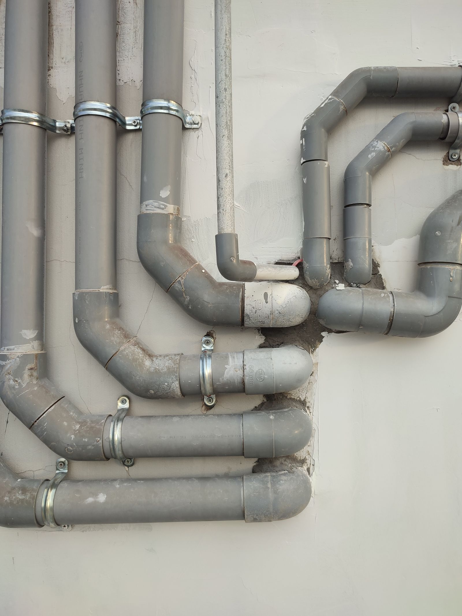
- Fittings. A 90° elbow, a T-piece, a reducer or a check valve are converted into an equivalent pipe length — one sharp 90° elbow corresponds to roughly one to two metres of straight pipe. Ten elbows are therefore like adding ten to twenty extra metres of pipework.
- Valves and equipment. The filter, the multiport valve, a heat exchanger, a salt chlorinator. A clogged filter adds losses continuously — which is why the pressure gauge is a diagnostic instrument, not a decoration (see Filtration pressure and what the gauge tells you).
Hence the design rule: keep the run as short as possible, with a minimum of fittings, and wherever you can, use two 45° elbows instead of a single sharp 90° one. A plant room close to the pool saves more energy than a pump one class more expensive. The differences between filter types are discussed in the article Sand vs. cartridge filtration.
Jet placement: how many there should be and where they should point
A return jet with a standard connection size can reasonably carry around 4–6 m³/h. The number follows simply from that: divide the required flow rate by this value. A 45 m³ pool with a flow rate of 7.5 m³/h will manage with two jets; an 80 m³ pool with a flow rate of 13 m³/h needs three. In practice one more geometric rule is added: place the jets so that no point in the pool is more than 5–6 metres from the nearest one.
The basic placement principle is unambiguous: the jets belong on the opposite side from the skimmers. The aim is for the flow to push surface debris towards the skimmer, not away from it. In a rectangular pool the jets are usually placed in the shorter wall or along one of the longer ones, so that a gentle circular movement of the whole volume is created.
Two details that are often overlooked:
- Installation depth. A jet approx. 20–30 cm below the surface mixes the surface layer but does not reach the floor. A jet installed too deep, on the other hand, leaves the surface standing still. The compromise is an adjustable jet angled slightly downwards, which creates a helical movement.
- Angle and orientation. All jets pointing in the same direction create circulation. Jets pointing against each other cancel each other out and stagnant water forms in the middle.
Where dead zones form
A dead zone is a place that treated water practically never reaches. You can recognise it by sediment settling there, by a film forming or by algae — even when the chlorine and pH values are fine. Typical locations:
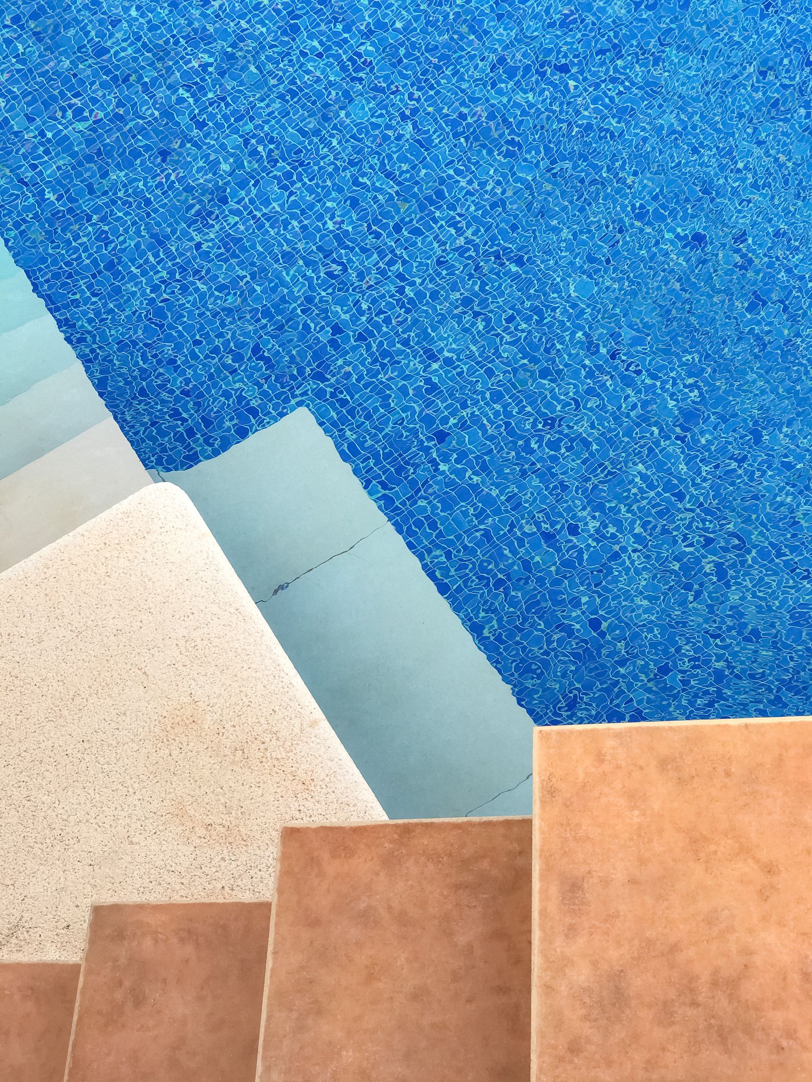
- Steps and the entry platform. The most common problem of all. Steps are hydraulically shielded, the flow goes around them and calm water remains underneath. The solution is a jet installed so that the flow runs along the steps, or a separate jet directly in the stairway area.
- The corners of the pool, especially the corner furthest from the jets and against the direction of circulation.
- The area directly below the skimmer and along its axis — water flows in here but does not mix.
- The vicinity of a counter-current unit, benches and shallow areas, where the geometry creates a pocket.
- The floor at the deepest point, if there is no main drain.
It is precisely dead zones that lie behind the impression that “the chemistry isn’t working”. The disinfection does work — it simply does not reach that spot in sufficient concentration. Before you start increasing the dosage, check the circulation.
Main drain and skimmer: roles that cannot be swapped
The main drain is not merely an outlet for emptying the pool. In operation it is half of the suction. It draws the coldest and most heavily loaded water from the floor, prevents sediment from settling and ensures that the whole volume is filtered, not just the upper layer. A pool without one does work — but at the price of more frequent vacuuming and poorer temperature homogeneity.
The skimmer, by contrast, draws from the surface, where most of the organic pollution concentrates: pollen, leaves, sunscreens, grease. Its efficiency stands or falls with the water level — it must reach roughly two thirds of the height of the opening. A few centimetres lower and it draws in air; a few centimetres higher and the surface film cannot get past the flap. Covered in detail in the article Skimmer: function and maintenance. The ratio of the two branches is regulated with ball valves; the recommended setting is roughly 50 : 50, and during heavy leaf fall the skimmer can be temporarily strengthened.
Counter-current units and water features need their own circuit
This is a mistake that appears regularly in designs: a counter-current unit, a massage jet or a mushroom fountain is connected to the main filtration circuit. It does not work. A counter-current unit needs a flow rate on the order of 50–80 m³/h — that is five to ten times what the filtration circuit of a family pool carries. It must have its own pump, its own suction and its own pipework of an appropriate size, typically 75 or 90 mm. Connecting it to the filtration run has two consequences: the filtration pump will not drive the counter-current unit anyway, and conversely the counter-current pump will overload a filter that is not sized for such a flow. We cover the details in the articles Counter-current unit for a pool and Water features in a pool.
Water turnover time vs. hydraulics
The turnover time indicates how long it takes for the entire volume of the pool to pass through the filtration. According to international practice (SPATA, FINA), 6 to 8 hours is chosen for private pools, 4 hours for public pools and 2 hours for children’s pools.
It is the hydraulics, however, that decide whether this value is realistic. With high pressure losses the pump shifts along its curve and the actual flow rate is lower than the one you calculated — the turnover gets longer without you noticing. And even with a correct turnover, badly aimed jets repeatedly filter the same water. A separate article is devoted to this topic: How long to run pool filtration.
Symptom, cause, solution
| Symptom | Probable hydraulic cause | Solution |
|---|---|---|
| The pump is noisy, “rattles”, there is air in the pre-filter | Cavitation — undersized or leaking suction, clogged basket, low water level | Clean the baskets, check the suction for leaks, throttle the discharge, in the long term increase the suction size |
| Sediment and algae around the steps and in the corners | Dead zone — the jets do not create circulation towards that spot | Redirect the jets, add a jet at the steps, help temporarily with a robot |
| The water is cloudy even though the chemistry is right | The real flow rate is lower than the design one, the turnover is not being met | Measure the pressure at the filter, evaluate the losses, extend the filtration |
| The skimmer draws in air, the flap “knocks” | Incorrect water level or too strong a suction from the skimmer | Top up the water, balance the valves between the skimmer and the main drain |
| High electricity consumption with little effect | High pressure losses — long run, many elbows, small cross-section | Simplify the run, increase the size, switch to a variable-speed pump |
| The surface “does not move” at one end | The jets point against each other and cancel each other out | Align the jets into a single circulation |
| The floor is cold, the surface warm | The main drain is missing or closed | Open the main drain branch, add one during a renovation |
What can be put right in a finished pool?
Pipe sizing set in concrete is final. A large part of the problems, however, lies elsewhere.
Solvable without building work: the orientation and angle of the jets, balancing the valves between the skimmer and the main drain, the water level, replacing sharp elbows in the plant room with gentler bends, adding a jet to an existing branch and, above all, switching to a variable-speed pump running longer at lower speeds — a lower flow velocity means quadratically lower losses and markedly lower consumption.
Only during a renovation: increasing the size of suction pipework set in concrete, adding a main drain, relocating the plant room, a separate circuit for a counter-current unit.
What will never fix the problem is a stronger pump. If a service technician offers you a more powerful motor as the solution, ask what the flow velocity in the suction line will be — and whether they have calculated it.
Frequently asked questions
Will a stronger pump increase the flow rate if I have 50 mm suction?
Practically no. The pipe cross-section is a fixed ceiling. A stronger pump will try to force more water through, thereby deepening the negative pressure in the suction line, and cavitation becomes a risk — noisy operation, impeller wear and fluctuating flow. The real gain in flow rate tends to be minimal, the gain in consumption considerable.
How many jets does an 8 × 4 metre pool need?
At a depth of 1.4 m this is roughly 45 m³ and a flow rate of around 7.5 m³/h with a 6-hour turnover. Two jets placed opposite the skimmer are the minimum, three give better circulation — especially if the pool has steps or an irregular shape. Geometry matters too, though: no point should be more than 5–6 metres from the nearest jet.
Does a pool have to have a main drain?
It is not compulsory in a private pool, but it significantly improves both the hydraulics and the temperature balance. Without one, it is mainly the surface that gets filtered, sediment stays on the floor and the cold layer does not mix. If you are building a new pool, a main drain belongs in the design — retrofitting it is only possible during a renovation of the floor.
Can I identify a dead zone without measuring instruments?
Yes. Switch on the filtration, drop a few leaves or a drop of food colouring onto the surface above the suspect spot and watch where the flow carries them. If they do not move towards the skimmer within a few minutes, circulation does not reach there. Sediment settling in the same place every time is an equally reliable indicator.
Why isn’t my chemistry working even though I dose correctly?
In a pool with dead zones the disinfectant is distributed unevenly: there is plenty of it in the flow and little in the stagnant water. Increasing the doses does not solve the problem, it only raises costs and loads the water. First check the circulation and the real flow rate, and only then adjust the chemistry.
Conclusion: hydraulics belong in the design, not in improvisation
The circuit design is the only part of a pool that cannot be added later without demolition. It takes an hour at a desk — calculate the volume, choose the turnover time, derive the flow rate from it, derive the pipe size from the flow rate at the given velocity, add up the pressure losses and only at the very end select the pump. In exactly this order. The reverse procedure, where the pump is bought first and the pipework is “whatever was in the warehouse”, is the most common reason why a pool hums, eats electricity and has cloudy corners for its entire life.
If you are dealing with new equipment or modernising your existing setup — variable-speed pumps, filtration, valves and pipework — you will find it all in the category pool equipment.
